Filling the landscape with Solar Utility Nodes.
Open sourcing the solution of small scale electrification.

Friday, March 22, 2013

The Power of the Panel


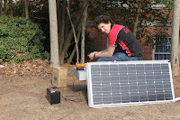
Today we took to the lawn behind the prototyping lab to test the output of our solar panel under good conditions.  It was bright and sunny, and between about 4 P.M. and 5 P.M. we took measurements of current and voltage.  It was bright and sunny, and we saw the highest current we've drawn thus far out of our solar panel: 5.8 amps.  The solar panel is rated at an optimum operating current of 5.29 amps, and our range was about 3 amps to 5.8 over the hour.
Whoo!  Amperes!


Connecting a load, we charged Julian's and my phones, drawing 230 milliamps to charge my phone on its own (a Samsung U450 Intensity) and 660 milliamps for the two phones (Julian's is an iPhone 4S) charging together.  We're still a little unsure as to the prioritization of load v. battery charging when a load is connected in parallel to the battery.  In this case, the current through the battery decreased by the amount of current through the two phones (as expected) but it's unclear whether the phones drew the current they wanted (the phones draw about 660 milliamps charging from a wall anyways) or if the battery in the circuit would decrease the current flow to the load if they tried to draw more current.  Continuing with this project, we're trying to figure out ways to direct the current flow between the two charging options in order to optimize use. 

1. The PWM5 is the solar charge controller for us.  The CMP12, for the third time in a row, failed to yield any current drawn out of the solar panel, despite the sun being out and strong.  Given that we've been working in a relatively stable environment (the engineering quad doesn't get too crazy), we have no interest in risking inconsistency with our node.  The PWM5 has been working well and consistently; it's also sealed very well so dust and water don't pose a problem.  The CMP12 has lots of holes in its interface that could allow dust in, and it's many components could fail fairly easily with exposure to dust.  Our only concern with the PWM5: it is rated at a maximum of 6 amps.  Today, we saw a current of 5.8 amps drawn from the solar panel, and it was late in the afternoon and not the strongest sunlight that we'll see.  We're trying to get in touch with the manufacturer of the PWM5 to see if they really mean that you can only run 6 amps through it.

Maximum current aside, we're considering including some LED-type indicator for the current leaving the solar panel (so operators can know if they have a strong current and could use the time to charge phones, run lights, and charge the battery, or if they should prioritize charging just the battery) and for the voltage across the battery (charge percent of battery).  This will allow for maximizing efficiency and preventing users from running out of battery power in the middle of the night without being aware of the low level of the battery.

2. If one of the 36 mini squares on the face of the panel (see picture below: there are four rows of nine squares clearly visible) has a significant part of its area in shadow, the current coming out of the solar panel drops considerably.  With a current of 5.2 Amps, covering 1 square dropped the current to 1.4 Amps.  A few minutes later, covering 2 squares dropped a 4.9 Amp current to .8 Amps.

This seems to indicate that each of the squares on the face are connected in series, so that blocking sunlight to any single square will impact the total current by more than linearly proportional to the blocked area.  A hypothesis is that a certain amount frequency or  intensity of light is needed to activate the semiconductor to allow any current to flow regardless of that particular cell contributing to current output. This is a wonderful thing to have discovered before any attempt to install the solar panel and be thwarted by a single ill-placed branch.


Moving Forward:
Our next step is to work on the box.  We feel confident in our panel itself and in our choice of the PWM5 as our solar charge controller.  So coming soon: putting these phone charging circuits into action!

Phone Charging Circuit

The better method of dropping the voltage from a 12 V battery to 5 V for phone charging to use a 5 V voltage regulator. The circuit shown below does this. To put 2.8 V and 2 V on pins 2 and 3 respectively a resistor voltage divider can be used because very little current is drawn from them. The phone uses these pins to know if it is plugged into a computer or a wall charger and so only weak strength is required. R5 in the circuit corresponds to an extremely high resistance circuit that the phone would use to measure the voltage of the data pins. The load resistor corresponds to a phone.


It is important to note that the circuit diagram and simulation uses a LT1086-5 voltage regulator which is not what we actually used. From Radioshack we bought the 2 LM7805C ($2 each) regulators which are a more general purpose component. The plot below corresponds to the simulation of this circuit which shows that the the nodes have the correct voltages and that only 1 A is being drawn from the battery. Since 1 A is drawn through the regulator and 7 V are being lost there is a power dissipation on the regulator of 7 W. This means it gets very hot very quickly which is a loss of power but there does not seem to be many ways of getting around this effectively. We actually put two of these regulator in parallel for testing to dissipate the heat better.


This 1 A is essentially the maximum current that a phone will use to charge and to my knowledge only the iPhone uses this much current. It is more likely that in our project we will encounter older (non-smartphone) Samsung and Nokia phones which usually do not use more than 500 mA. The charger for the Samsung Intensity U450 is rated an 800 mA output but upon testing it seemed that the phone actually only uses 415 mA to charge. The photos below shows the small charge monitoring circuit which we built. It is simply a USB cable connected to a phone charger which feeds its 4 pins into a bread board. We can then make measurements of current and voltage while rerouting the pins into the phone for charging.


The voltage regulator circuit was quickly tested on a bread board and was able to test below. The photo below shows the initial circuit.


While this circuit works and it was necessary to learn about how phone charging is done to day there is an alternative way to charge phones. It is very easy to buy small phone chargers designed for cars which therefore run on 12 V. These devices usually drop the 12 V to 5 V in a more efficient way too. They use larger a full PCB to drop the voltage rather than one integrated circuit. We are considering using the charge featured in the photo below and it would be simple to modify the unit to use a cable and connector to plug into the node rather than the usual car socket. This device, although more expensive, "should" be less prone to breaking.


Sunday, March 17, 2013

Phone Charging - Which Circuits NOT to Use!

I have been doing some experimenting with phone charging. Unfortunately there is no one charger fits all when it comes to phones but what is good is that today every company seems to be gravitating towards the USB charging protocol because phones are now expected to be able to be charged by computers. The silver bullet for phone charging is to simply have an inverter which will step up the deep cycle 12 V up to 115/240 V AC. Then you can plug in the charger that you bought with your phone and away you go.

The problem with this system is that you step up DC voltage to high AC voltage and then immediately bring it back down to even lower (5 V) DC. This is hugely inefficient and since we are working off solar panels and deep cycle batteries we are aiming to be as energy efficient as possible. So the solution to this is to drop the 12 V from the battery to the most standard possible phone charging protocol which seems to be the 5 V USB plug.

Something well documented on the internet is what pins do what for USB phone charging. Most phones just charge when pin 1 has 5 V and pin 4 is grounded. Pin 1 is the right most pin when you are looking into the USB socket and the protruding pin board is in the lower half of the entire socket. See the Wikipedia page to double check. For something as picky as iPhone however the middle two data pins actually make a difference. The iPhone will charge at 0.5 A if it connected to a computer. The way it detects this is by measuring the voltage on the middle two pins which should both be 2 V. If the iPhone is connected to the wall then is should measure 2.8 V on pin 2 and 2 V on pin 3 and then charge twice as fast at 1.0 A. Keeping this in mind a charger should be made which gives pin voltages 1-4 as 5, 2.8, 2, 0 V.

So what sort of circuit can be used to drop 12 V from the battery to 5 V for phone charging. The first thing that any electrical engineer will learn is how to construct a simple resistor voltage divider. You can workout your ratio of resistors very easily if you want them all in series by deriving the voltage division equation for each node and then reducing the matrix that they make. So for a voltage source across the dividing resistors of Vs, output voltage for a specific node of Vo, you can write down the equation Vo = Vs( Rfuture/(Rpast+Rfuture)) where Rfuture represents the resistance which your conventional current is yet to go through and Rpast is resistance which is the conventional current in that branch has already traversed.

Very quickly with some simple analysis you will notice something. If you attach a load to a voltage divide which is of considerably lower resistance than the resistors in your voltage dividing circuit then you have completely changed the voltage that each node is supposed to have. LTSpice is excellent (and FREE) circuit modeling software and so I double checked my hypothesis and as expected, adding a low resistance load (or a low resistance resistor) completely changed the intended node voltages. It is like shorting some of the resistors in your divider out of the circuit altogether.

So the other option, if you are set on going down the voltage divider path, is to make the resistors in the divider comparable to the load resistance. Since the max load of a phone charging is roughly 1 A for a 5 V source, Ohm's law will give you an effective resistance of 5 Ω. Making your divider resistors comparable to 5 Ω will leads to your circuit catching fire if you are using a deep cycle battery. A simple model of such a circuit is shown in the image below. (click to enlarge)


This circuit maintained the desired voltages on each node but these are extremely low resistances to be letting a lead-acid battery get into contact with. The plot of the node voltages and currents which are a result of this circuit is shown below and as you can see the total circuit current is over 7 A! This will destroy your circuit if your using the common 1/4 Watt resistors and furthermore that is a huge waste of power to be charging a phone at 1 A. We are running our phone chargers from a 35 Ah (amp hour) battery which means we can produce 1 A for 35 hours roughly. If we were to use the circuit above we would get around 4 hours of operation...which is useless. (definitely click to enlarge)


Th next post will be about better approaches to phone charging and after testing what is probably going to be used in mini power node.

Saturday, March 16, 2013

Conceptual Diagram of System

The image below shows a sketch of how the system might be installed in a home. The solar panel is mounted on the roof and connected to the central power distributor (CPD). The CPD will be able to divert the current from the solar panel to the battery or the load. The CPD will also house all the connections to the lights, which are spanned across the house via cables, and the USB ports for phone charging. If something fancy like a Raspberry Pi gets incorporated into the deal then that will also exist in the CPD.


The box which contains all the of the CPD components will be easy to open and understand. This is vital to continue this notion of modularization. If a single phone charger was to malfunction within the CPD it should be easy to identify which charger and then detach it and install the new one which would arrive via mail.

Shopping

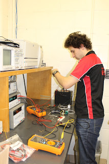
So after ordering various parts online and making trips to some local shops we got all the necessary parts to begin building and testing. We were fortunate enough to get lab space at in the Duke engineering buildings so we have plenty of power supplies, multimeters and electrical components. The list below outlines everything that we bought and relevant details.

  • DCM0035 Deep Cycle 12 V battery from Interstate Battery. Interestingly, these are the types of batteries used in wheel chairs. Not a bad sign because it means they are built for constant charge and discharge. Cost from a local dealer was $120.57.
  • Renogy 100 W monocrystalline PV solar panel from Amazon for $179.99.
                                                 

  • CMP12 Solar Autoswitch Panel charge controller, 10 A, 12/24 V from Amazon for $15.


  • MR11-xHP6-DI: 6 High Power LED MR11 Bulb MR11-WWHP6-DI: Warm White from Super Bright LEDs for $14.95.
     
  • MR16-xW4W-x: 4 Watt MR16 LED bulb MR16-WW4W-45: Warm White 45 degree from Super Bright LEDs for $14.95.
  • Optek LED STRIP, 3 LED, WHITE, 16LM from Element 14 for $3.31.
  • DS24 Bridgelux ES RECTANGULAR ARRAY, WARM WHITE, 1200LM from Element 14 for $8.37.
  • CREE - LED, PLCC4, WARM WHITE, 304MW, 8.6LM from Element 14 for $2.73. (10 pack)
Two types of solar charge controller were bought to test different aspects of reliability, easy-of-use and efficiency. Also 5 different types of LED lights were bought to test energy use, brightness and again easy-of-use/installation. Blog post to come will discuss the features of each of these items.

To-Do (Prototyping)


Our first day in the lab and we have (in addition to testing the basic functionality of our solar panel-battery-solar charge controller system) made a To-Do list for the remainder of the prototyping process:

 
·      Debugging: how do we make it very clear when something has failed, and what has failed?
·      Relative efficiency of different phone chargers: is it worth it to use different charging mechanisms/switchboard?
·      Lights: what wires work best (efficiency over length)?
·      Solar charge controller: which solar charge controller should we use?  The PWM5 vs. CMP12
·      Housing: how will we package the node?  How do we emphasize modularity?
·      Layout: record the schematics of our circuitry, what things connect to what.
·      Deployment: moderate stress testing with dust/water/etc. 
·     Outputs: range of current/voltage output for overcast/full sun days, time to charge battery augmented by drawing charge during the


Friday, March 15, 2013

The Value of the Node

-->
In order to allow lasting impact, our node has to have some level of community buy-in, whether it’s a financial investment in further technology or just the adoption of ownership of the technology that we bring with us this summer.  After our month or so working with the community and node, someone must decide that this is a valuable enterprise.

A huge part of that is confidence in the technology we are bringing. We must make the node extremely modular in the sense that it will comprise of a set of units which are easily assembled and detached. The benefit of this is that is some part of it is to fail (perhaps the charge or lights controller) then the owner of the node can quickly send back the faulty part and new part can be mailed back immediately.

No technical knowledge about the device would be needed to remove, install or even debug any part of the unit. The interface needs to be made such that it is obvious which part is not working and how to exchange it.  We also aim to prevent faults as much as possible. Hopefully we will have time to do strenuous testing on the node for things like rain and dust. Improvement in the casing and electronics can then be made to lower the chances of breakage. It is possible that we go to Nepal with this device and it would be during monsoon season, a real test of climate.

Beyond demonstrating the functionality and reliability of the nodes, we must show their monetary value.  A node owner is able to charge their phones or light their home, but we also envisioned our node being used as a small business with a “pay to charge” component.  Customers could pay a small amount per minute of charging during the day or night, and the owners responsible for its upkeep could collect this payment.

This brings us to the question of microfinancing.  We have to consider who gets this new technology, how do we sell/give it to people once people are interested in using it, and where will the money for repairs and new nodes come from? It was explained to us by Dr. Malkin, who works with Engineering World Health, that giving the node to a community to use as a public device is extremely risky because no single person is directly responsible for it and that such a system would rely on there being established leadership within the community. A far better solution seems to be to give the node to a family, which would then have incentive to protect its source of income.

In theory, the idea of small-scale loans for new technology is great.  It allows for the people most in touch with the needs of the community to benefit from new technology, without making the initial financial investment unrealistic.  However, in practice (and especially in our case since we aren’t a financial institution) things become much more complicated.  Introducing the need to keep up with payment schedules complicates the task from our end, and it’s very difficult to find success stories from microfinance endeavors in developing countries.

Determining the manner in which this technology is distributed initially and the way start-up costs are distributed is one of the main questions that we seek to address with continued research and exposure to a specific community.  This more than anything else in our project is highly situational and sensitive to the norms and culture of the specific community. While the rough figure of $400 (our current estimate for a node) could definitely be improved upon and made smaller this venture is really about documenting the implementation. We hope that people will be able to pick up where we finish to make the nodes better but also more economical with an even better financing model.

Technological Outline

The start of our project began with lots of research into what technology in the developing world is needed and what has been successful. The types of places we are interested in working in are very rural un-electrified villages which can be found in many countries from Nepal to Uganda. Today, these villages are typically near a city or large village which is electrified but may still be at an impractical distance to utilize regularly.

A very common need for people who are not in electrified areas is cell phone charging. This is something that has been picked up by many NGO's and start-up companies. For example Zamsolar is a start-up aimed at using solar energy to satisfy the demand for phone charging. Network reception and the phones themselves are becoming extremely common among most developing nations and unfortunately this sort of technology moves faster than infrastructure development. When Lydia and I were thinking about implementing beneficial technology in such areas this application immediately arose after speaking with various professors involved with similar ventures.

In some areas, but not all, lighting is also a priority or at least a decent benefit to the life styles of the locals. A group which specializes in this is the Himalayan Light Foundation (HLF) who, similarly to our project, use domestic solar panels for energy. With the advance of LED brightness over the last decade we are hoping to incorporate some simple house lighting into the node's features. LEDs are extremely long lasting, reliable and energy efficient which makes them perfect for this application.

The other thing that we are interested in was how we could use our node for telecommunication. Apart from cell phones FM radio is popular in almost every area of the globe and so a basic radio could be incorporated into the package. The utility of the internet is forever increasing as well. 3G networks are surprisingly not uncommon in un-electrified villages. Two Duke students last summer traveled to Togo to set up a solar powered internet cafe in a rural village in Togo. (see article here) They got internet from a local cell tower which was powered by an internal combustion generator refueled periodically.

The idea of bring internet to someones how through one of these nodes seems incredible. Since we do not have a location for our project yet we cannot guarantee what infrastructure will be in the area. If 3G is available that would could be used if the subscription is economical. Alternatively there are interesting projects being planned in Australia which provide internet to very rural areas through digital radio which would be very long range. If a transmitter could be set up in a local electrified city then this could be a window to the internet. A very cheap compact computer which has recently exploded on the geeky scene is the Raspberry Pi. These small devices could do the bulk of the signal processing required for a digital radio and also provide the needed hardware for accessing the internet.

Lydia and I aim to deploy our technology over a roughly 30 day period between May and June. Time is against us in terms of prototyping our node and so what we are determined to have implemented is the ability for house lighting and phone charging. The other features will be tested if possible. The next blog post to come shortly will be about financing and the social aspect to this project.